![]()
![]()
This is the story of Team Shephard and their quest for speed on the dry salt of Lake Gairdner in South Australia. Their desire to push man and machine to the limit.
Their journey began in 2005 when Allen Shephard and Boyd Kolozs saw the Dry Lakes Racing Association's annual Speedweek in action. This planted the seed and Allen decided his 1962 E-Type was perfect for the job.
The idea was simple - see how fast the E-Type could go. Over the next decade they tested themselves and the E-Type in the harsh environment of the Australian outback.
The book tells the story of the pursuit of speed, how they developed the car to go faster and the records they set and broke along the way. It is the story of salt lake racing on the edge.
This book is based on research spanning almost five decades. As such, the book is archaeological in nature, based more on observations of cars than on factory publications or other literature. The examination of principally un-restored cars, many partly or completely disassembled and still retaining their original configuration, permitted discovery of much detailed information not reported before. The subject is covered in depth, with 1568 pictures and 516 pages.
A few of the many topics treated in the book are:
This book significantly advances the understanding of the original configuration of these remarkable cars.
When I acquired the MK 2 the tachometer [as well as the oil pressure gauge] was not working. It became fairly obvious that one of the problems was that the tachometer [tacho] generator had a broken electrical connecting lug. This tacho generator uses the same principle as a pushbike generator to create electrical voltage by rotating a permanent magnet inside a coil. This electrical voltage is then fed to the tachometer instrument, which in reality is a voltmeter. The principle is that the faster the tacho generator goes the more electrical voltage is produced which produces a correspondingly higher reading that we see as revolutions per minute [RPM]
This same tacho generator is also used in the MK9, S type, earlier E types and Daimler 250. Enquiries for a replacement tacho generator part no C14996 resulted in prices in excess of $300. Hmm –it was time to put the thinking cap on and see if repairs could be affected.
An inspection of the terminal cap of the tacho generator, which uses push on spade connectors revealed that the lug had been broken off flush with the surface of the plastic cap. By using my trusty dremel tool I was able to excavate around this broken lug to a depth of about 4 to 5 MM or 3/16 inch. I was then able to cut the male section of a spade terminal down to a suitable size and solder it to the old lug. The whole thing was then finished off by using a dam of masking tape to allow a suitable build up of epoxy resin over the excavated area and the base of the new lug. This all resulted in a now sound lug projecting from the terminal cap.
I had checked the wiring from the generator to the tacho instrument and all measured OK with about 2.5K or 2500 ohms resistance, which indicated a correct circuit impedance existed through the instrument. I replaced the tacho generator [with a new O ring fitted] hooked up the tacho instrument, started the car and achieved nothing. The b.......y instrument was U.S. ! [unserviceable]. I was also able to check that the generator was working as Ben Stafford had lent me an old battered tacho with a partly broken needle etc. but still serviceable as an indicator and I hooked it up and it worked.
Muttering and cursing I removed the tacho instrument [and a couple of squre inches of skin as well]. I cleaned off the workbench which is a miracle happening in it’s own right and laid out some clean cloth to allow me to dismantle the tacho. It does come apart very simply as the faceplate only needs to be twisted to align the spaces on the faceplate with the lugs on the case. The faceplate can then be lifted off. The tacho instrument itself is only secured in the case with two screws and the clock at the bottom can be left attached to the case.
Applying gentle pressure to the needle revealed that it would move but was rather bound up on the “jewels” or pivots. In my time as a radio technician and later on in aircraft engineering I had been exposed to and qualified to do instrument repairs. One facet of instruments that few people ever consider is that they do need lubrication. More particularly so as they get older and the original lubricants dry out. With an artists brush I applied some penetrating oil to each of the needle pivots and allowed it to take effect. After about an hour the needle was quite free and I applied some sewing machine oil to each pivot. The needle was now quite free and I reassembled the instrument. I made a temporary connection between the tacho generator and instrument, started the engine and wonders to behold it all worked.
Tearing off the usual square inch of skin in the process I refitted the tacho and reconnected the wiring. A quick check ensured that all was functioning and the beer fridge in the shed was raided to celebrate.
A JDCQ member had a problem with his Jag 420 series brakes. The power boost system appeared to have failed and it required incredible pressure to stop the car. We got involved in a diagnosis one morning with the car upon his hoist and to be very honest it took a fair bit of effort to sort out the problem.
What appears to be a dual brake system is not quite what it seems. The master cylinder is in fact a single primary system that then feeds pressure and air information to the remote power booster system where the system becomes dual. Each primary and secondary system has its own hydraulic reservoir.
The power booster system uses vacuum on both sides of the air piston. A remote air valve mounted on the primary master cylinder supplies vacuum on the drive side of the piston but when the master cylinder is depressed introduces ambient air pressure to the drive side of the piston hence assisting the hydraulic brake action. Heath Robinson would have been proud of this arrangement.
The final diagnosis was that the air piston/diaphragm in the booster unit was leaking badly. By serendipity another acquaintance was "parting out" a 420 with a good booster and this was acquired to get the car back on the road while a more extensive overhaul takes place on the original booster.
It should be noted that we discovered that a number of E types from roughly 1965 on share the same braking system.
I have been intrigued by an on going problem in the 1960s model Jaguars such as MK 2, S type, E type, 420 etc. The main area of concern is the oil pressure gauge. This is an electric device that was apparently Smiths first foray into the domain of electrical transmitted oil pressure. Apparently the Jag Enthusiasts Club in England has also been following up on this problem.
To say that the Smiths electric oil pressure gauge is an accurate instrument would be taking the truth very lightly. It is one of the most Heath Robinson devices I have ever encountered in any instrumentation. Normally an instrument transmitter contains a device a bit like the variable resistor used in volume controls in a radio. These are generically referred to as "potentiometers". As the temperature or pressure changes the variable resistor feeds more or less voltage to the gauge in your dash panel to make the indication. Simple enough?
However Mr. Smith put a whole new twist on the scene by using a system in his oil pressure transmitter that works as follows. The flexible diaphragm in the transmitter has an electrical contact on the diaphragm. When oil pressure expands the diaphragm this contact connects to another contact on the end of a bi-metallic strip. This makes a circuit through a heating wire wound around the strip which heats up until the bi-metallic strip bends and breaks contact with points on the diaphragm.
The bi-metallic strip then starts to cool down and straightens out until contact is made again and the process repeats. The more oil pressure there is the longer it takes for the strip to heat up and therefore the more electric current runs through the system. This current is measured and shown on your oil pressure gauge as pounds per square inch!
The bi-metallic strip system is well known and is used in the majority of "flasher" units in directional indicators in motorcars. However they do not last forever and eventually they fail due typically the points burning out. It is an electro/mechanical device and as such will never be a stable source of information for a gauge system.
Why I am making this point is that an old oil pressure transmitter can give quite erroneous readings. One club member was really quite concerned with his oil pressure in an XK series motor in a MK2, which only ever got to about 40 PSI cold and was flat out making 20 PSI when hot. The engine was generally in good order and was not rattling or giving any typical signs of distress associated with clapped out Jag engines. On my suggestion he obtained a direct reading after market gauge and coupled it up in place of the electric system and was delighted to find that all of the above pressures were just about doubled.
I have also run across this problem and have had widely divergent readings from different transmitters. In fact I trust the older Bowden Tube direct reading oil pressure gauge used in early Jags like the MK5, 7, 8 and MK 1 any day against one of these later electrical devices.
The good news is that a company by the name of CAREBONT in England have purchased the rights and tooling for early Smiths gauges and have redesigned the oil pressure gauge for these 1960s Jags. This kit apparently consists of a completely new transmitter and gauge using modern techniques but looks just like the original. It is not cheap at around 70 pounds or about A$200 [Australian] dollars but the current price for a new oil gauge transmitter to fit the old system is A$130 so it would be worthwhile going the extra dollars for something new, reliable and accurate.
Extractors (also known as “headers”) might be the ultimate, but what can I do to improve my exhaust system without spending a fortune?
After experimenting with several system configurations on a series 1 E-Type I found that a straight through system in which the centre silencers were replaced with 600 mm resonators worked for me.
Resonators come in several guises, but I used the following: A perforated pipe passing through a larger body with the space between packed with fibreglass. I kept the pipe diameters 1-3/4” all the way to the rear. This offers much less resistance to flow than the standard system. The result is “street legal” for sound under modest power, but can make a delightful growl when provoked. The standard rear resonators were retained.
The inlet and outlet ends of the original twin centre silencers are offset and not opposite one another. Therefore, if your front pipes are to the original pattern, the above idea will result in the pipes not being quite parallel. Over the length of the car this will not be noticed. Incidentally, the twin exhaust pipes should exit under the reversing light at 6 inch centres.
This modification upgrades the headlights and adds a relay in both the high and low beam circuits so that the headlight switch, the dip switch, and the flasher switch do not carry full headlight current.
Use two 30 amp relays (e.g. Narva part No. 72386). These are mounted on a home-made bracket attached to the left hand stud holding down the padded dash top behind the centre dashboard swing-down panel.
Malcolm Sayer’s Intent Reinstated?
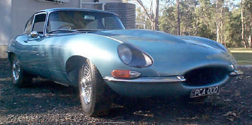
Malcolm Sayer’s C, and D-Type designs are wonderful examples of the design dictum that “form follows function”. However, in the case of the Series 1 E-Type, I feel that the beauty of its otherwise functional lines is marred by the addition of chrome plated finisher rings to the headlight apertures.
You can give your E-Type the smooth appearance of the C and D-Type Jaguars by fitting flush-mounted Perspex headlight covers. I like to imagine that this would have been Sayer’s original intent.
(The chrome rings look like something which the Marketing Department thought was necessary to appeal to the US market.)
The following actions are required (all work is reversible):
1. Remove the offending headlight finisher rings, glass covers and rubber gaskets.
2. Remove the chrome beading from between the mudguards and the bonnet centre section. (With the finisher rings removed, all four beads are too short.)
3. Weld closed the holes for the screws which fastened the finisher rings to the bonnet (the captive nuts remain in place).
4. Prepare and repaint the bonnet.
5. Make the moulds on which the Perspex headlight covers will be formed. These are moulded on the original glass headlight covers, but have to be enlarged because, without their rubber seals, the glasses are smaller than the recesses in the bonnet. I made male moulds. Proceed as follows:
5.1 Grease the inside of the glass headlight covers and cover them with cling wrap.
5.2 With the concave side up, make a dam around the periphery of the headlight covers. I used a "ring" of flexible plastic strip wound around the covers and secured with duct tape.
5.3 Pour cement into mould. I used about 3:1 sand to cement and put some wires in the cement to reinforce it.
5.4 After the cement has set remove the mould from the glass headlight covers. Remove any cling wrap from mould.
5.5 The mould is smaller than the finished Perspex cover needs to be, so the perimeter of the mould is enlarged using body filler. Also any imperfections in the surface of the mould are corrected with body filler. The surface of the mould must be perfectly smooth.
6. Form the Perspex covers as follows from 2.8 or 3 mm thick Perspex:
6.1 The mould is placed on a brick on an oven tray.
6.2 Perspex, cut oversize, is placed on the raised mould. It is important to keep the amount of oversize to a minimum. The Perspex is supplied with a protective plastic film over it. This is left in place. A finely woven cotton cloth is also placed over the Perspex.
6.3 A fibreglass flywire is now placed over the cotton cover. This flywire hangs below the edge of the Perspex. (The function of the cotton cover is to prevent an impression of the flywire being left on the surface of the Perspex.)
6.4 Apply even downward force all around by hanging steel chain from wire hooks around the perimeter of the flywire. (The purpose of the brick mentioned at point 6.1 was to give clearance for the hanging chain.)
6.5 Place the oven tray in your home oven. Bring to 160ºC. (best done while spouse is absent). When the oven is up to temperature, the bending of the Perspex can be assisted by a gloved hand.
6.6 Leave the mould in the oven and allow it to cool slowly back to room temperature. Slow cooling is very important. Excessive distortion of the headlight cover will result if it is removed from the mould before it is absolutely cold.
6.7 Remove the Perspex cover from the mould.
6.8 Trim excess Perspex and shape the covers to fit the recesses in the headlight apertures. (The Perspex is cut and trimmed using an angle grinder.)
6.9 You will find that the headlight covers are not exactly the same shape as the moulds. They will bend down along their sides more than the original glass. (As the Perspex cools it pulls down onto the mould at its edges rather than shrinking away from the mould.) This is actually an advantage for the reason given at point 8.
7. As a gasket, apply self-adhesive closed cell neoprene foam strip to the recesses in the headlight apertures.
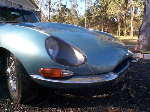
8. Drill the Perspex covers and the recess in the bonnet aperture to suit the self tapping screws which will retain the Perspex covers. Two size 6 self tapping screws is all that is needed. The greater curvature of the moulded Perspex than the original glass means that when secured front and rear on the main axis of curvature the sides will pull firmly down into the foam gasket. The sides will flex back to the required shape, and you will find that only two stainless steel self tapping screws are required for each cover. These can be seen in the accompanying photo.
9. Fasten the Perspex covers to the headlight apertures. (Use hard self tapping screws to cut the initial thread before inserting identical stainless steel screws.)
10. Purchase two long chrome bonnet beads (BD 19029/1).
11. Fit the new long chrome beads. (The beads are supplied longer than necessary and have to be cut to length.)
12. Use one of the previously removed long beads to make two short beads.
13. Fit the short beads to the bonnet.
14. It would be a nice touch to turn up a couple of stainless steel plugs to close off the leading edge of the long beads just above the headlights. I haven’t got around to doing this yet.
15. Over a period of time the Perspex tends to craze where it is in contact with the neoprene foam gasket. This appears to be promoted by the action of sunlight. To retard this crazing, the outside perimeter of the Perspex over the neoprene seal could be painted with a satin black paint. Again I haven’t done this yet. This will happen when I eventually make replacement covers.
The Result - This photo shows the two size 6 screws which hold the cover. The over-riders and motif bar have also been removed. But that's another story
Have you noticed how the fibreglass transition from the air cleaner to the carbies on E-Types is usually damaged where it is Pop riveted to the two internal mounting brackets.
The cause of this problem appears to be that the fibreglass compresses slightly due to the force applied by the Pop rivet. Eventually vibration causes a slight movement of the fibreglass under the head of the rivet. The fibreglass starts to chafe, the rivet holes enlarge and eventually the rivets pull right out.
The fix I have employed is as follows: Drill the heads off the rivets and punch them out. Then, at each rivet position, glue a bush into the fibreglass. The bushes are only as long as the fibreglass is thick (about 3 mm) and have an outer diameter less than the rivet head. A simple fixture can be made to maintain the correct location of the eight holes. I used a polyurethane adhesive (Sikaflex), but an epoxy adhesive such as Araldite should be OK.
After the adhesive has set, scrupulously clean the inner face of the fibreglass around the sleeves. Now glue a flat piece of steel approx. 0.5 mm thick with matching holes over each pair of bushed holes. A bit of zincalume or colourbond is quite OK for this job. Use a polyurethane adhesive (e.g. Sikaflex). The purpose of the steel backing is to spread the load at the fastener rather than to have it concentrated at the point of fixing.
You can now firmly rivet through these holes confident that you will have a permanent sound joint.
A similar technique can be used at the four mounting holes of the fibreglass fan cowling. These are bolt holes, but the same principle applies.
The previous article sets out details for the fan upgrade for the Series 1 E-Type. Those who undertake this job might run into another problem caused by arcing across the contacts of the fan relay. This article describes the cause of this problem and how to overcome it.
When the fan is running and the fan relay contacts open, a high reverse voltage is induced across the relay contacts and arcing results This process eventually causes a build up of metal on one contact and a crater on the other. The contacts of my relay actually welded themselves together with the result that the fan came on and remained on when I switched the ignition on, regardless of the engine temperature. I was able to break the “welded” connection by tapping the side of the relay, but this was not a permanent solution.